(a) We have designed and implemented two wireless sensor network platforms named Octopus II and Octopus X. The Octopus II consists of a TI MSP430 microcontroller running at 8MHz, 10KB of RAM, 1MB of Flash memory and a Chipcon CC2420 radio operating at 2.4GHz with an indoor range of approximately 200 meters which is compatible with the IEEE 802.15.4 standard and Zigbee. The Octopus X is implemented by CC2430. The CC2403 is a true System-on-Chip (SoC) solution specifically tailored for IEEE 802.15.4 and ZigBee applications. The CC2430 combines the excellent performance of the leading CC2420 RF transceiver with an industry-standard enhanced 8051 MCU, 128 KB flash memory, 8 KB RAM. The technology of Octopus II and X had been transferred to two IT Corporations. And the Octopus platforms are widely been used over twenty Universities including Taiwan University, Tsing Hua University, Chiao Tung University and Cheng Kung University. Both sensor platforms have become the designated platforms of the 2008 call for proposals of the Technology Innovation and Integrated Applications for Wireless Sensor Networks Research Projects which are sponsored by the National Science Council of Taiwan.
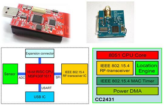
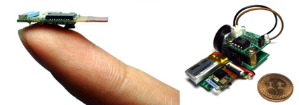
(b) This research team has also developed the smallest platform in the world, “Eco,” that is not only applied in Taiwan but also used as a wireless sensor platform by international research teams such as UC Irvine, USA and University of Zaragoza, Spain.
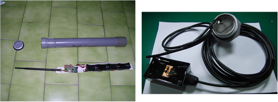
(a) We have used the developed wireless sensor platforms to monitor debris flows, with cooperation with the GIS Center of Feng Chia University. Using wireless sensor networks, it is possible to lower the cost of deployment and maintenance for debris flow monitoring. Our debris flow monitoring system, as shown below, consists of two devices, INSIDER and COORDINATOR.
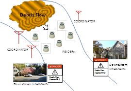
INSIDER has a rugged package to be placed on the riverbed. When debris flow comes, INSIDER will drift along with the flow, continuously record data, and transmit data to the COORDINATOR on the riverbank. Our low-power design allows the system 150-days of continuous operations even without sunlight, resulting in low maintenance cost. The COORDINATOR is responsible for coordinating the transmission of INSIDERs and their time synchronization. The design has been tested in Jiangjiagou, Yunnan.
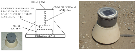
(b) We have developed techniques for rapid and stable outdoor deployment of wireless sensors. We have designed a self-configure, low-complexity, and low-power multi-hop protocol, including an efficient data collection protocol that does not require pre-set topology. Under the conditions that the total number of sensors is smaller than 20, our system can cover an area of 200 m x 200 m and provide basic data redundancy and 100% data delivery (including retransmission), without pre-configuration and routing table. The wireless sensors will be deployed near Heping Township, Taichung County, for ecological monitoring of construction works.
In this project, we have developed a Grid middleware, called Unibox. We use Unibox to integrate over 20 research institutes in Taiwan to form Taiwan UniGrid System, which is the first Grid system designed by researchers in Taiwan. The UniGrid system provides a series of services, such as storage service, information service, computing service, etc., and web-based user interfaces for users to use its computing and storage resources. The system architecture of UniGrid is shown in Fig.3-1.
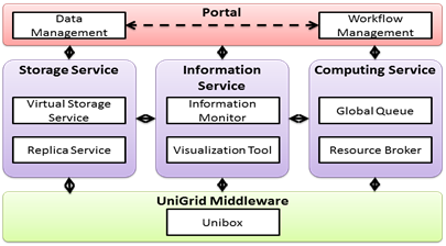
Fig. 3-1. The system architecture of UniGrid
In this project, we use Grid and P2P techniques to integrate the computing and storage resources of all hospitals to form a Medicare Grid Platform. On top of MGP, we developed an electronic health record (HER) system and three services, namely Decision Support System (DSS), Intelligent Mobile System (IMS), and A wearable Personal Health Protection System (PHPS). The computing Grid of MDP can fulfill the computing requirements of hospitals. The P2P-based data Grid of MDP has a very good security and fault tolerance capability. It is also efficient in data search and manipulation. For the EHR system, the data format used in this system can be transformed to another data format used by the medical information system of a hospital and vice versa. For the DSS, it uses data mining and gene sequence alignment techniques to develop a gene database related to cardiovascular disease to help physicians to do disease diagnostic. For the IMS, it was developed for the location tracking of patients in hospital based on the integration of RFID technology, MDP system and wireless network. For the PHPS, it was developed for measuring patients’ physiological conditions under a convenient and comfortable circumstance by using biomedical signal sensors and textile technology. The system architecture of Medicare Grid System is shown in Fig.3-2.
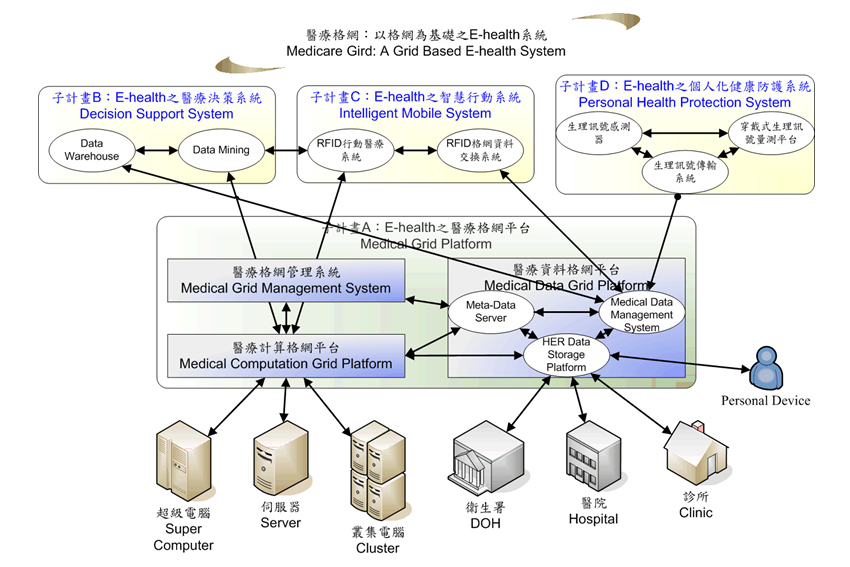
Fig. 3-2. The system architecture of Medicare Grid System
To achieve the collaboration with distributed resources among multiple grid systems, we adopt the super-peer network into a P2P meta-grid system, named Pisces, to form self-organization and self-management autonomies. The system architecture of Pisces is shown in Fig. 3-1. Pisces proposes a cross-grid layer built on top of existing autonomic grid systems to realize the Grid-to-Grid federation. By adopting a separate layer, Pisces can integrate with existing grid systems without modifying the original mechanisms and policies. Each grid system in Pisces is responsible for coordinating local resources and negotiation with other remote grid systems by the P2P technology. With the convergence of grid systems and P2P paradigm, Pisces is able to harmonize autonomic grids and improves the scalability of a grid federation.
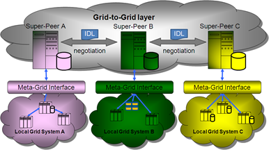
The system architecture of Pisces
在此提出的多功能N對N節點全光封包交換技術(N-to-N OPS),其架構如圖1所示。在此架構中裡的每個輸入埠,根據特別規劃的時間延遲與預定輸出埠構築而成的傳輸控制,我們利用可調式波長轉換器(tunable wavelength converter, TWC)將輸入的光封包轉換至指定波長。在經過N對1光結合器(N-to-1 combiner)之後,用一組三埠光循環器(3-port optical circulator)將所有的光封包自輸入埠導向光學緩衝器。這部份的光學緩衝乃是由光纖延遲路徑(fiber delay lines, FDLs)以及寬頻光纖布拉格光柵(wideband FBG, WFBGs)所組成。其中,寬頻光纖布拉格光柵可使用寬頻的多通道光纖布拉格光柵(multichannel FBG, MFBG)或取樣光纖布拉格光柵(sampled FBG, SFBG)。由於光纖布拉格光柵的反射特性,每個封包會在光纖延遲路徑中來回傳遞一次。因此,每一份的光纖延遲只須要提供封包延遲所需時間的一半。為使光學緩衝能提供儲存(M – 1)個封包的容量,我們採用(M – 1)段的光纖延遲路徑及M組寬頻光纖布拉格光柵。每一組的寬頻光纖布拉格光柵皆能反射一整組WDM波長訊息,這組WDM波長位於輸出端所使用的陣列波導光柵(arrayed waveguide grating, AWG)的一個自由頻譜區域(free spectral range, FSR)之中。如需不同的時間延遲,只要把封包波長轉換至不同自由頻譜區域的波長區間中即可獲得適當的延遲。在系統的輸出端,藉由陣列波導光柵的濾波與自由頻譜區域之特性,每個陣列波導光柵的輸出埠皆具備在光頻譜上以自由頻譜區域為間隔的週期濾波功能。因此,被緩衝的光封包就能經由1對N陣列波導光柵(1 x N AWG)路由至預定的輸出埠。
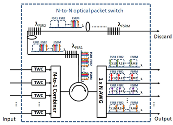
圖1:提出架構的示意圖與波長分配
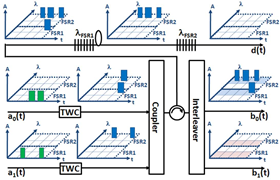
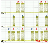
這樣的光學封包交換機具有許多不同的交換功能。例如圖2所呈現的是先進先出多工(first-in-first-out multiplexer, FIFO MUX)功能。假定不同封包在交換機裡發生衝突(contention)時,a0(t)輸入埠的封包擁有較高的優先權。我們預計使抵達a0(t)與a1(t)兩個輸入埠的光封包皆路由到輸出埠b0(t),如圖2所示。因為兩組封包同時抵達,且a0(t)的優先權較高,故在輸入埠a0(t)的第一個封包並不需要延遲,並被轉換為波長λ11,即是在波長分配策略之下第一個自由頻譜區域的第一道波長。另一方面,輸入埠a1(t)的第一組封包與剩下的其他封包必須延遲一個時間區塊(time slot)。所以,這些封包的波長會被轉換為第二自由頻譜區域的第一道波長,λ21,以確保能獲得一個時間區塊的延遲,並且在輸出埠b0(t)輸出。其實驗的結果,在輸入埠與先進先出多工輸出埠的封包序列呈現於圖2(b)。
(a)
(b)
圖2:先進先出多工 (a)波長配置與(b)提出之光封包交換的實驗結果展示
在此,如圖3(b),我們將展示線性場域調變(linear field modulation)及直接偵測(direct detection)之虛擬單邊帶正交分頻多工(virtual SSB-OFDM, VSSB-OFDM)傳輸,其中一射頻頻率(RF tone)被設置於此單頻帶的下緣。相較於圖3(a)所呈現的傳統的光正交分頻多工,此技術可大幅增加頻譜效益。藉由反覆的估計與消除(iterative estimation and cancellation)演算技術,在接收端訊號對訊號拍頻干擾(signal-to-signal beating interference, SSBI)可以被抵消掉,如此可以減緩以往為了隔離訊號對訊號拍頻干擾而帶來的頻譜間隔(frequency gap)需求,並且節省一半的電訊號頻寬,故具有極高的頻譜效益。我們推導了虛擬單邊帶正交分頻多工的理論模型,並且針對接收端反覆獲取的訊號處理過程進行詳細的分析。模擬的結果指出,相較於之前強度調變模式的單邊帶正交分頻多工(SSB-OFDM),在我們提出的架構中,具有將近2 dB的光訊雜比(optical SNR, OSNR)增益以及較強的色調色散(chromatic dispersion, CD)容忍力。在實驗方面,我們與美國南加州大學Alan Willner教授所帶領的光通訊實驗室(OCLAB)合作研究。在本次的實驗中,我們成功地將10 Gbps的4-QAM虛擬單邊帶正交分頻多工訊號,不經過色散補償,在標準化單模態光纖(standard SMF, SSMF)裡傳送340公里。其實驗架構與結果如圖4所示。我們發現經過傳輸的訊號幾乎沒有犧牲任何訊號的品質。此實驗結果顯示,與以往的技術比較,我們這樣的方式可以在光訊雜比的表現上獲得5 dB的改善。
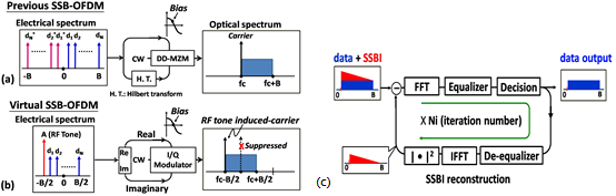
圖3:(a)先前強度調變模式的單邊帶正交分頻多工、(b)提出的虛擬單邊帶正交分頻多工和(c)虛擬單邊帶正交分頻多工中反覆估計與消除的技術
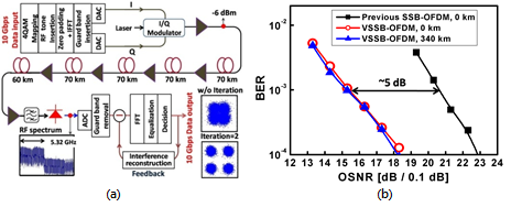
圖4:(a)實驗架構與(b)虛擬單邊帶正交分頻多工的實驗結果
N×N (N = 16)負載平衡交換核心的架構如圖5所示。以框架為基礎的封包透過負載平衡交換卡傳輸而且儲存於線卡的虛擬輸出佇列(VOQ)。負載平衡卡將封包轉換成均勻分佈的流量。第二個交換卡根據對稱交換配對將封包送到目的地輸出埠。為了避免封包輸出時的順序紊亂,封包在虛擬輸出佇列的位置被反饋到輸入埠。封包的來回傳輸時間(包含了負載平衡卡,虛擬輸佇列以及交換卡的傳輸延遲)必須要低於一個框架時間。
在這個工作中,我們已針對以回授為基礎的4×4負載平衡交換核心開發了一個低傳輸延遲,低功率以及有效面積利用率的架構和電路。相較於傳統配對演算法N×N交換機所需O(N3)的硬體複雜度,在這個交換機設計,只有使用到兩個D型正反器(DFFs)以實現訊框產生器。在負載平衡交換機中使用對稱式交換配對,線卡和交換機之間可建立一條提供封包維持順序的回饋路徑。回饋路徑上的延遲時間需要低於一個框架時間以利封包組成正確的順序。從架構設計觀點,我們建議不要使用SERDES而是直接從高速領域去設計交換積體電路以降低延遲。從電路設計的觀點,電流型邏輯(CML)輸出緩衝器導入PMOS主動負載以及主動後端終端。CML-DFF堆疊電流源以及對稱拓撲被採用以提昇交換速度。從實作的結果來看,這個工作全部的傳輸延遲從29.5ns降低至僅僅0.8ns,佔用矽面積的80%以及消耗功率的80%。交換機的流量高達32Gbps(或8Gbps/頻道)。
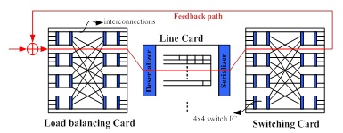
圖5:由4×4交換積體電路所建構的16×16交換核心
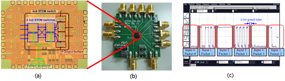
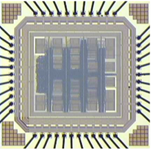
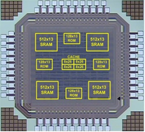
圖6:低傳輸延遲的4×4交換核心積體電路及其量測結果 (a)裸晶照、(b)交換模組以及(c)量測結果
經過數年的辛苦工作,我們已在先進電信運算架構機櫃中完成了一個負載平衡布可夫馮紐曼交換機的原型,如圖8所示。採用了雙星背板架構,我們的先進電信運算架構機構從每個遠端線卡槽提供了兩路10-Gbps SERDES連線分別到中央的兩個交換槽。我們也設計了一個可以程式化為線卡或是交換核心的18層印刷電路板硬體平台,如圖7所示,以實現一個8個結點的負載平衡布可夫馮紐曼交換機。符合先進電信運算架構的規格,我們的印刷電路板使用廣泛應用於電信企業中的48伏特直流電源。除此之外,我們的印刷電路板設計支援當交換機在運轉時允許將線卡插入先進電信運算機櫃並自動從快閃記憶體載入程式的熱插拔能力。
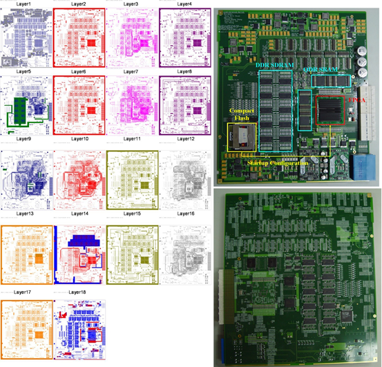
圖7:我們的先進電信運算架構機櫃線卡實作(前視和背視)以及18層印刷電路板
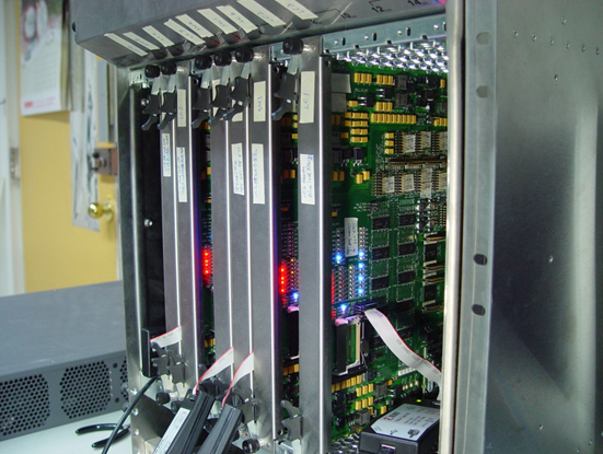
圖8:我們在先進電信運算架構機櫃中的負載平衡布可夫馮紐曼交換機原型
- Low complexity space-time-trellis-coded MIMO decoder algorithm and MISO decoder implementation
- The first STTC coded MISO decoder in the world
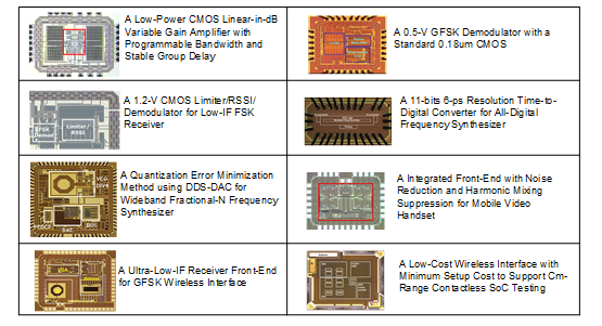
- IC:
- Framework:
- Ultra low power FFT processor design and implementation
- The most power efficient FFT processor in the world
- IC:
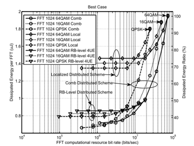
- Performance:
MIMO-OFDM Wideband Video Transmission Systems for Super HDTV:
- Super HDTV transmission SoC platform design and implementation
- Won the NSoC project award
- System:
- Quality:
- SoC Implementation and Demonstration of Multi-user MIMO WiMAX Baseband Transceiver:
- Baseband MIMO transceiver conforming to IEEE802.16e-2005
- Suitable for SISO/MIMO with variable subcarrier allocation
- Best performance when published
- 200k gate count complexity reduction (~45% chip area reduction)
- Low power consumption (2.3Mbps/mW) with high throughput (60Mbps)
- Achievements:
- 2009 DAC/ISSCC student design contest winner
- First prize at Phenix IC design contest
- Technology transfer to industry
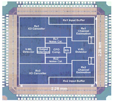
- IC:
- System:
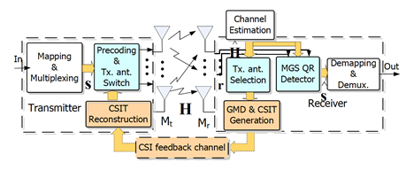
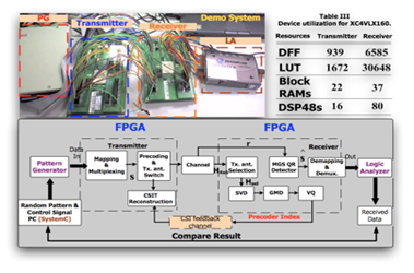
- Design and Implementation of Closed-Loop MIMO Communications:
- Combine GMD and Antenna selection to boost performance, 1.5 dB gain over ML and 6 dB gain over V-BLAST
- Reduce over 50% complexity compared to the conventional antenna selection scheme
- Reduce greatly the feedback information (from 80 bit to 7 bit under 4x4 MIMO)
- Provide high reliable low complexity QR detector
- Provide 120 Mbps throughput under maximum frequency 50 MHz with FPGA implementation
- 2010 ASP-DAC university design contest winner
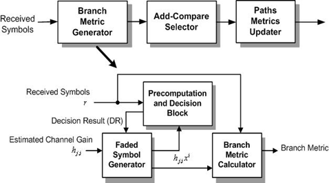
- Block diagram:
- System:
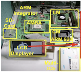
- Wireless Front-end Chip Prototype:
- Video Encoder/decoder (H.264):
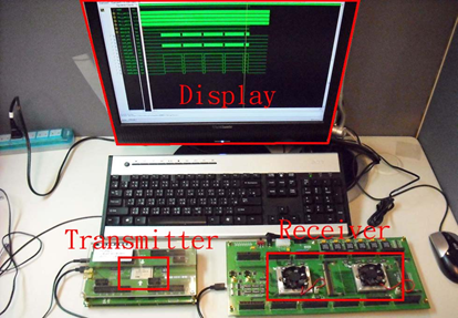
- Wireless Test System:
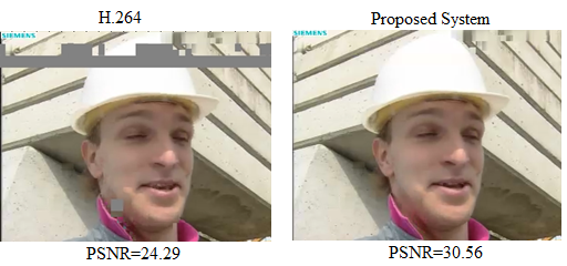
In the past a few years, NTHU has developed the highest video decoder resolution up to 3840x2160 which is 4 times large than the state of the art HDTV. In addition, the encoder developed in NTHU also has the lowest power consumption compared to other state of the art video encoder. Because of the superiority of the encoder and decoder, the H.264 hardcore has been licensed to industrial companies and also has been integrated in a notebook PC with real demonstration.
As the evolutional technology, HOY wireless test system achieves more than ten times reduction of VLSI testing and verification by utilizing contactless techniques. The project involves collaboration of faculty members and researchers between EE and CS departments, developing and integrating low-cost wireless/contactless communication and advanced embedded design-for-test circuitry. Our test system maximizes the production yield by supporting wafer test, final test and repair, which can be implemented in a very low-cost portable device and successfully replaces the traditional monster tester of tens of million dollars. During the pass four years, our achievements include 15 patents, more than a hundred technical papers, and 5 technology transfers to the industry. We also received the 2009 National Invention Award, ROC (Silver Plate) and 2010 MXIC Golden Silicon Award (Silver Plate). In addition, a spin-off company has been founded to leverage our technologies. Based on the novel wireless test platform, we are collaborating with many research institutes, including ITRI, CIC, UCLA, UCSB, and so on, to develop next-generation technologies of VLSI verification and testing for system yield and quality.